What Are the Top Pneumatic Operated Valve Types?

A pneumatic operated valve turns compressed air into a practical means of controlling flow. It can open, close, or regulate a line without placing an electric actuator at the valve. The right choice depends on more than pipe size. Pressure, fluid, temperature, cycle frequency, and the required failure position all matter.

The market context is substantial, but broad figures need careful reading. Grand View Research’s Industrial Valves Market Size, Share & Trends Analysis Report estimates the global industrial valves market at USD 79.4 billion in 2023, with projected growth through 2030. That figure covers industrial valves generally, not pneumatic-operated valves alone. It signals the scale of valve use, not a precise forecast for this category. Hans D. Baumann, a recognized control-valve specialist and author of Control Valve Primer, emphasizes in his work the importance of matching valve performance to process requirements. That principle is easy to overlook when a catalog’s dimensions appear to fit.

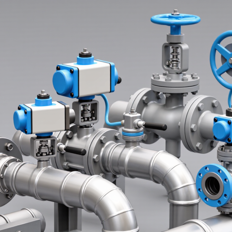
This guide compares common types, including ball, butterfly, globe, and diaphragm valves, along with their pneumatic actuation options. A compact quarter-turn ball valve may suit fast isolation, while a globe valve can offer more controlled throttling. The same actuator does not make these bodies interchangeable. Small details matter. Air supply, actuator sizing, accessories, and maintenance access can change the outcome. One limitation deserves attention: no general ranking can replace an application-specific review. The sections ahead explain where each type works well, what trade-offs to check, and which questions help narrow the selection.
What Are the Top Pneumatic Operated Valve Types?

How Pneumatic Actuation Opens and Closes a Valve

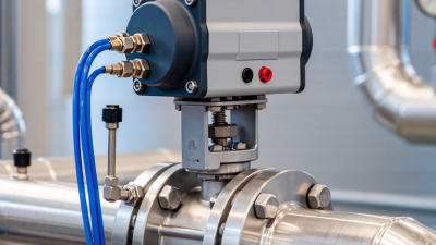
Pneumatic actuation uses compressed air to move a valve’s stem or shaft. A control signal operates a solenoid valve, which directs air into an actuator chamber. Air pressure pushes a piston or diaphragm, creating movement. That movement turns a ball or butterfly valve, or lifts a linear valve’s stem. Air does the work.

For quarter-turn valves, a rack-and-pinion actuator commonly rotates the shaft through 90 degrees. Linear actuators move a stem up or down, as used with many globe valves. A single-acting actuator uses air in one direction and a spring in the other. A double-acting actuator uses air for both opening and closing. The right choice depends on valve design, required force, and operating conditions.

A practical detail matters: “fail-safe” does not describe every pneumatic setup. A spring-return actuator may move to its configured position when air is lost, but that position depends on its design. Double-acting units generally need air for movement in either direction. Check the actuator’s pressure range and the valve’s required torque or thrust before installation. Small mismatches can cause slow or incomplete travel.

Tips: Watch the valve indicator during a test cycle. Listen for air leaks, and confirm the valve reaches both end positions. If movement feels sluggish, check the air supply and tubing before changing settings. It is easy to blame the actuator too soon.

What Are the Top Pneumatic-Operated Valve Types?

Ball, butterfly, and plug valves commonly use quarter-turn pneumatic actuators. Globe, gate, and diaphragm valves commonly use linear actuators. The chart shows the ideal force a pneumatic piston can produce as supply pressure increases.

How opening and closing work: Compressed air moves an actuator piston or diaphragm, turning a valve shaft or moving a valve stem. A double-acting actuator uses air pressure to move in both directions; a spring-return actuator uses air for one direction and a spring for the return. Actual output force is lower than the ideal values shown because of friction, spring load, and other losses.

Key Features Used to Classify Pneumatic Valves

What Are the Top Pneumatic Operated Valve Types?
Key Features Used to Classify Pneumatic Valves

Pneumatic valves are classified by how they direct air, how they move, and how they are controlled. Port and position designations show the flow paths: a 3/2 valve has three ports and two positions, while a 5/2 valve commonly operates a double-acting cylinder. A 5/3 valve adds a center position, which may block, exhaust, or pressurize selected ports. Check the actual flow diagram; labels alone can be misleading.

Actuation is another key feature. A single-acting valve uses air for movement in one direction and a spring for return. A double-acting valve uses air for both directions. Valves may also be direct-acting or pilot-operated, with pilot designs using a smaller control signal to shift the main mechanism. Internal construction matters too: spool valves can provide multiple flow paths, while poppet designs often seal tightly. Port size, operating pressure, flow capacity, response time, and mounting style help determine whether a valve suits a specific system. Real installations are less tidy than diagrams, so allow for pressure loss and contamination.

Tips: Match the valve’s function to the actuator, then compare its flow rating with the cylinder’s demand. Check the fail position and air quality requirements. Test under operating conditions; a valve that works on a bench may behave differently in a long, narrow air line.

Pneumatic Ball and Butterfly Valve Types

Pneumatic Ball and Butterfly Valve Types

Pneumatic ball valves use an actuator to rotate a drilled ball, typically through 90 degrees. The straight-through bore offers low flow resistance when fully open. Floating-ball designs suit many general duties, while trunnion-mounted designs support larger sizes or higher pressure needs. Actuators may be spring-return or double-acting. Spring-return models move to a defined position when air supply fails, but the required fail position depends on the process. Check the valve’s pressure rating, seal material, and actuator torque together. A mismatch can cause leakage or unreliable movement.

Pneumatic butterfly valves turn a disc inside the pipe, making them compact and practical for larger lines. Concentric designs often serve general water or air service. Double-offset and triple-offset designs reduce disc contact during opening and can suit more demanding conditions, depending on seat and material selection. They usually need less space than comparable ball valves, though the disc remains in the flow path. That detail matters in some systems. There is no universal winner. A catalog description may look clear, yet actual performance depends on media, temperature, pressure, and cycle frequency. I would verify those conditions before selecting an actuator or valve style; assumptions can be costly.

Pneumatic Globe, Diaphragm, and Pinch Valve Types

Pneumatic globe, diaphragm, and pinch valves handle flow in different ways. A globe valve moves a plug toward a seat, making it useful for precise throttling. Its curved flow path can create more pressure loss than a straight-through design. Check the required flow range, not just the pipe size. Small details matter.

A diaphragm valve presses a flexible membrane against a weir or seat. The process fluid stays separated from the actuator, which can help when handling corrosive or hygienic fluids. The diaphragm is a wear part, though; temperature and repeated cycling affect its service life.

A pinch valve closes a flexible sleeve, leaving few internal obstructions. It can suit slurries or fluids with suspended solids, but sleeve wear needs regular inspection. Keep it simple: confirm the material suits the fluid.

On site, also check air pressure, actuator response, and the valve’s behavior if air supply is lost. A selection that looks obvious on a drawing may prove awkward to maintain in a cramped installation. That deserves a second look.

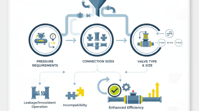
How to Select a Pneumatic Valve for an Application

Choosing a pneumatic valve starts with the job it must perform. Ball and butterfly valves suit many on/off duties, while globe valves offer more precise throttling. Diaphragm and pinch valves can help handle fluids that may clog or damage other valve designs. The right choice depends on the process, not just the pipe size.

Check the fluid, operating pressure, temperature, flow rate, and how often the valve will cycle. Then confirm the actuator can deliver enough torque or thrust at the available air pressure. For a control valve, consider how accurately it must regulate flow; for isolation, check its shutoff requirements. Specify the desired failure position, too: should the valve open or close if air is lost? A common selection mistake is sizing from line diameter alone. It can cause poor control or excessive wear. Ambient heat, moisture, and limited maintenance access also matter.

Tips: Share real operating ranges with the supplier, not only normal values. Check air quality and connection details. If data is uncertain, measure it first; a tidy spreadsheet can still hide a bad assumption.

What Are the Top Pneumatic Operated Valve Types? - How to Select a Pneumatic Valve for an Application

Compare common valve designs operated by pneumatic actuators. Actual pressure, temperature, flow, and material limits depend on the specific valve construction and must be verified against its technical datasheet.

Valve Type Typical Operation Common Applications Key Advantages Selection Considerations
Pneumatic Ball Valve Quarter-turn; commonly on/off, with modulating control possible when fitted with a suitable positioner and actuator. Water, air, gas, and compatible liquid services in process, utility, and isolation systems. Fast operation, compact installation, and generally low flow resistance when fully open. Check seat and seal compatibility, allowable pressure and temperature, port configuration, and whether the application needs tight shutoff or throttling.
Pneumatic Butterfly Valve Quarter-turn disc motion; used for isolation and, in suitable designs, flow regulation. Large-diameter water lines, HVAC systems, air handling, and some compatible process services. Lightweight and compact relative to many other valve designs, particularly in larger pipe sizes. Consider disc and seat materials, pressure drop, flow characteristics, shutoff requirements, and whether the disc is suitable for the fluid and operating conditions.
Pneumatic Globe Control Valve Linear stem movement; commonly paired with a positioner for continuous modulation. Process flow, pressure, or temperature control where repeatable throttling is required. Well suited to modulating service; trim options can be selected for different flow and control requirements. Assess required flow coefficient, rangeability, pressure drop, cavitation or noise risk, trim material, and actuator thrust.
Pneumatic Diaphragm Valve A flexible diaphragm moves against a weir or seat; actuator designs may provide on/off or control operation. Corrosive, viscous, or particle-bearing fluids, as well as applications that benefit from isolating the operating mechanism from the process fluid. The diaphragm can separate the process fluid from the stem and other upper valve components. Confirm diaphragm material compatibility, temperature limits, pressure rating, solids handling needs, and whether the flow path suits the service.
Pneumatic Pinch Valve Pneumatic pressure compresses a flexible sleeve to stop or regulate flow. Slurries, powders, granules, and fluids containing suspended solids, where compatible sleeve materials are available. The sleeve provides a simple flow path and can keep the process medium away from many valve body components. Verify sleeve compatibility, abrasion resistance, operating pressure, temperature, and expected sleeve replacement interval.
Pneumatic Gate Valve Linear movement raises or lowers a gate; generally intended for fully open or fully closed service. Isolation in compatible pipeline services where low obstruction in the fully open position is useful. Provides a relatively unobstructed passage when fully open in suitable designs. Usually not the first choice for routine throttling. Check actuator thrust, operating speed, installation space, and shutoff requirements.
Pneumatic Check Valve Typically self-actuated by flow or differential pressure; some specialized designs use pneumatic assistance or control. Preventing reverse flow in pumping, compressed-air, and process systems. Can help protect equipment and reduce reverse flow without continuous manual operation. Confirm the valve is genuinely designed for pneumatic operation if an air actuator is required. Check cracking pressure, orientation, flow direction, and dynamic operating conditions.

Application checklist: Define the fluid and its compatibility requirements; operating and design pressure and temperature; pipe size and connection; required flow capacity and control accuracy; shutoff class; cycle frequency; available instrument-air pressure; and the required failure position. Spring-return actuators can move to a defined position on loss of air when correctly configured; double-acting actuators typically require air pressure for movement in both directions. Confirm the complete valve-and-actuator assembly against the application datasheets.

Scroll to Top