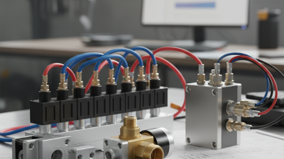
How to Choose a Pneumatic Valve Positioner

Choosing a pneumatic valve positioner is not just a matter of matching a model number to a valve. The positioner must translate the controller’s signal into accurate stem or shaft movement, even when process pressure, friction, or vibration changes. Béla Lipták, a process-control engineer and editor of the Instrument Engineers’ Handbook, is associated with a practical principle: “Select instrumentation for the behavior of the process, not merely the equipment label.” This wording is a paraphrase, not a verified verbatim quotation.

Start with the application. Check the actuator type, available air pressure, required travel, control signal, and fail-safe action. Then consider the process itself: a sticky valve on a hot steam line may need different attention from a small water-control valve in a quiet utility room. Look at accuracy, response, air consumption, environmental protection, and whether local feedback or diagnostics matter to maintenance staff. Small details count. A mounting bracket that shifts can undermine careful calibration.

This guide will explain how to compare these factors and avoid common selection mistakes. It will also distinguish pneumatic positioners from electro-pneumatic models, since the input signal and installation requirements differ. A catalog can make every option look simple. Real service rarely is. Check the instrument’s specifications against the valve and actuator documentation, and ask the supplier to confirm compatibility when details remain uncertain.
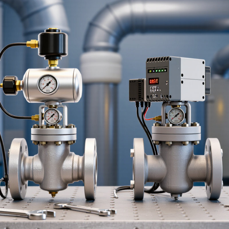
How to Choose a Pneumatic Valve Positioner

Understand the Role of a Pneumatic Valve Positioner

How to Choose a Pneumatic Valve Positioner

Understand the Role of a Pneumatic Valve Positioner

A pneumatic valve positioner helps a control valve reach the position requested by a control system. It receives a signal, adjusts air pressure to the actuator, and checks the valve stem’s movement through mechanical feedback. If the stem stops short, the positioner can add air to correct the difference. This feedback helps the valve respond more accurately as process conditions change.

Small errors matter. A valve that repeatedly misses its target may cause uneven flow, temperature swings, or slow control. For example, a sticky stem can resist movement even when the actuator receives adequate air. A positioner can compensate within its operating limits, but it cannot repair damaged packing, poor alignment, or a leaking air line. In the field, checking tubing and connections is often as important as adjusting the instrument.

When choosing a positioner, consider the actuator type, required control signal, available air supply, and operating environment. The positioner must match the valve assembly and provide suitable feedback across its travel range. Also distinguish control action from fail-safe behavior: the actuator and its configuration generally determine where the valve moves after air or power loss. It is tempting to focus only on precision. Yet a simple, well-matched setup may perform better than a complex one that is difficult to calibrate and maintain.

Match the Positioner to the Valve and Actuator

A pneumatic valve positioner must match the valve’s travel and the actuator’s motion. Check whether the valve is linear or rotary, then confirm the actuator’s stroke or rotation, spring range, required thrust or torque, and air-to-open or air-to-close action. A positioner with the wrong feedback linkage may hunt or give inaccurate travel. Small mismatch, big trouble. Verify that the positioner accepts the control signal and supply pressure specified for the installation; do not assume existing tubing or settings are suitable.

Actuator sizing matters just as much. The positioner must deliver enough air to move the actuator under the valve’s actual process load, while the actuator must provide adequate force or torque at the available supply pressure. The U.S. Department of Energy’s 2016 Compressed Air Sourcebook notes that compressed air can account for up to 30% of electricity use at some industrial facilities. That figure is not a positioner-performance rating, but it supports checking air use and leaks rather than treating instrument air as free.

Tips: Before ordering, record valve travel, actuator type, fail position, input signal, and available air pressure. Compare them with the positioner’s published limits and verify the feedback assembly on the installed valve. A bench test helps, though it cannot fully reproduce process forces. I would recheck the sizing after major trim or actuator changes; that step is easy to miss.

Check Control Signals and Required Performance

How to Choose a Pneumatic Valve Positioner

Check Control Signals and Required Performance

Start by matching the positioner’s input to the controller’s output. Many systems use a 4–20 mA signal, while some installations use pneumatic signals or digital communication. Confirm the signal range, wiring, and any split-range settings before ordering. Small mismatches can leave a valve moving through only part of its travel. Check the actuator type, too: a linear valve and a quarter-turn valve may need different mounting and feedback arrangements.

Then define the performance the process actually needs. A slow-moving utility valve may not require the same response as a valve controlling pressure in a fast-changing line. Look at accuracy, deadband, repeatability, and response time, using real operating conditions where possible. A highly sensitive setting is not always better; it can make the valve hunt around its target. Test the positioner with the actuator and valve together. That detail is easy to miss.

Consider air supply pressure and quality, plus the available space for tubing and maintenance access. Dust, vibration, and temperature can affect performance over time. In practice, catalog figures rarely tell the whole story. A reading that looks excellent on paper may feel different once piping, friction, and actuator sizing enter the picture. Record the signal and travel during commissioning, then compare them with actual process behavior. Some judgment remains.

Assess Operating Conditions and Compatibility

A pneumatic valve positioner must suit both the actuator and the conditions around the valve. Check actuator type, travel, mounting pattern, and available linkage before comparing models. A mismatch can cause sluggish movement or prevent the positioner from completing the valve’s full stroke. Small details matter. Confirm whether the actuator is single-acting or double-acting, and match the positioner’s output arrangement and failure response.

Then compare the site’s air supply and control signal with the positioner’s requirements. Supply pressure may fluctuate during peak demand, so use measured operating values rather than assumptions. Check the input signal range, air quality, and whether filtration is available nearby. Dust, moisture, vibration, and temperature swings can affect performance over time. An outdoor valve exposed to rain needs suitable environmental protection; a unit near a vibrating pump may need sturdier mounting. These factors are easy to underestimate on a drawing.

Compatibility should also be checked against the actual installation, not just a specification sheet. Verify clearances, tubing connections, and access for calibration and maintenance. If the valve operates slowly or cycles frequently, consider whether response settings and actuator sizing are appropriate. A neat match on paper is not always a perfect fit in the field, so confirm critical dimensions and operating limits before ordering.

How to Choose a Pneumatic Valve Positioner - Assess Operating Conditions and Compatibility
Assessment Dimension Operating Conditions to Confirm Compatibility Checks Selection Guidance
Control signal Identify the controller output and whether it is analog, pneumatic, or digital. Common inputs include 4–20 mA, 3–15 psi (0.2–1.0 bar), and digital communication options. These are not interchangeable without the appropriate positioner. Choose an input that matches the control system. For 4–20 mA installations, check whether a separate power source or a specific wiring arrangement is required.
Instrument-air supply Record the available supply pressure, pressure fluctuations, and air quality at the installation point. Many industrial positioners are designed for supply pressures within roughly 1.4–7 bar (20–100 psi), but allowable ranges vary by model. Confirm the positioner and actuator limits. Provide clean, dry air at the pressure specified by the equipment documentation. Use suitable filtration and pressure regulation where required; do not exceed the lowest-rated component.
Actuator type and action Determine whether the actuator is diaphragm or piston type, and whether it is single-acting or double-acting. Check the positioner output arrangement, port connections, actuator spring action, and required fail position. Select a positioner configuration that matches the actuator’s air ports and operating action. Verify that loss of air or signal produces the intended safe position.
Valve travel and feedback Establish the valve’s required linear travel or rotary angle and the available mounting space. Confirm that the feedback lever, shaft coupling, travel range, and mounting kit suit the valve and actuator geometry. Use a compatible mounting arrangement and ensure the feedback mechanism can cover the full stroke without binding or reaching its mechanical limits.
Actuator sizing and output capacity Review actuator volume, required operating force or torque, and expected stroking time. Compare positioner output capacity and flow capability with actuator demand and the available air supply. Choose a unit capable of driving the actuator through its full travel at the required response rate. Check whether a volume booster is needed for large actuators or faster response.
Process and ambient temperature Consider the local ambient temperature, solar exposure, vibration, and heat conducted from nearby process equipment. Check the positioner’s specified operating-temperature range and the ratings of seals, electronics, display, and accessories. Select a model rated for the actual site conditions. Add suitable shielding or installation measures if temperatures exceed the equipment’s specified limits.
Moisture, dust, and corrosion Assess indoor or outdoor installation, washdown, humidity, dust, salt exposure, and corrosive atmospheres. Check enclosure protection, materials, cable entries, connectors, and any required corrosion-resistant construction. Choose an enclosure and materials suited to the site. Confirm that covers and cable entries are correctly sealed after installation.
Hazardous-area requirements Determine the area classification, gas or dust group, temperature class, and local regulatory requirements. Verify that the positioner and associated electrical equipment have approvals suitable for the exact classified area and installation method. Use only equipment with the required certifications and follow the applicable wiring, grounding, and installation rules.
Control performance Define required positioning accuracy, repeatability, response speed, and expected control-loop behavior. Review the positioner’s performance specifications and compatibility with the actuator, valve, signal, and process dynamics. Match performance to the application. Excessively fast or aggressive tuning can cause hunting; commissioning adjustments may be needed.
Maintenance and commissioning Consider access for calibration, diagnostics, air-filter maintenance, and future replacement. Check configuration tools, local indicators, feedback setup, spare-part availability, and the required commissioning procedure. Prefer a configuration that maintenance personnel can safely inspect and service. Follow the equipment instructions for calibration and functional testing.

Plan Installation, Calibration, and Maintenance

How to Choose a Pneumatic Valve Positioner
Plan Installation, Calibration, and Maintenance

Plan the installation around the actuator, valve travel, and available instrument air. Check that the positioner supports the control signal and the actuator’s action, then confirm its mounting arrangement fits the valve yoke. Leave room to reach adjustment screws and fittings. Small details matter. Keep air tubing short, secure, and free of sharp bends; a kink can slow response. Use clean, dry air at the pressure specified in the equipment documentation. A common field mistake is blaming the positioner before checking for a leak or a loose feedback link.

Calibrate only after the valve and actuator are installed and the process is in a safe condition for testing. Apply the control signal at its low and high limits, and compare the valve stem travel with the expected endpoints. Adjust zero and span as directed by the manufacturer, then test several intermediate signals. Watch the stem, not just the display. If movement hunts or lags, inspect tubing, linkage alignment, and air supply before changing settings. Do not rush. Small calibration errors can affect control.

Set a maintenance schedule based on service conditions, not just the calendar. During inspections, look for moisture in air filters, cracked tubing, loose fasteners, and corrosion around fittings. Record signal, travel, and any adjustments so future checks have a useful baseline. It is easy to overlook a sticking linkage when the valve still moves. If symptoms persist, consult the equipment manual or a qualified technician rather than repeatedly increasing air pressure.

How to Choose a Pneumatic Valve Positioner: Plan Installation, Calibration, and Maintenance

Typical 4–20 mA control signal mapped to 0–100% valve travel. Use this linear reference during calibration; confirm the required action, travel range, and setup against the valve and positioner documentation.

Scroll to Top