A pneumatic solenoid valve sits where electrical control meets compressed-air movement. It may look like a small metal block, yet it can start a cylinder, release a clamp, or redirect air within milliseconds. Understanding this device begins with a simple question: how does an electrical signal create mechanical motion?
Industrial automation consultant John Rinaldi offers a useful practical reminder: “Good pneumatic design begins with understanding the air, not just the valve.” His point matters because a pneumatic solenoid depends on more than its coil. Supply pressure, flow capacity, port size, seals, tubing, and air cleanliness all influence performance. A valve installed on a dirty line may stick. An undersized valve may move an actuator slowly. The wiring can be correct, but the machine can still behave badly.
Inside the valve, an energized coil creates a magnetic field. That field moves a small plunger or pilot mechanism. The movement opens or closes an internal air path. When power is removed, a spring usually returns the mechanism to its original position. This sequence sounds neat. Real systems are less tidy. Pressure fluctuates, exhaust silencers clog, and moisture can damage sensitive components.
This guide explains the main pneumatic solenoid designs, their operating cycles, common port configurations, and practical selection factors. It also examines normally closed and normally open valves, direct-acting and pilot-operated models, response time, voltage, and maintenance. The goal is not merely to define the component. It is to show what happens inside the valve, at the tubing, and finally at the moving actuator.
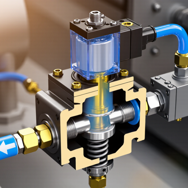
A pneumatic solenoid valve is an electrically controlled device that directs compressed air through a system. It opens, closes, or changes airflow when an electrical signal reaches its coil. In practical equipment, this action controls cylinders, grippers, clamps, and other air-driven mechanisms. The valve does not create pressure. It only manages the pressure supplied by an external compressor or air reservoir.
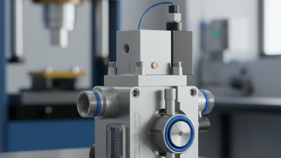
Its core components include the valve body, coil, plunger, spring, seals, ports, and internal orifices. The body contains the airflow passages and usually carries clearly marked inlet and outlet ports. Around the plunger, the coil creates a magnetic field when energized. This field moves the plunger, changing the position of the internal seal.
A spring returns the plunger when power stops, unless the design uses another control method. Seals must tolerate the working pressure, temperature, and air quality. Small particles or moisture can cause leakage.
A useful inspection starts with the pressure rating and the valve’s normal position. A normally closed valve blocks air without power; a normally open valve allows it. This distinction affects safety and machine behavior. Port size also matters, because a narrow passage can restrict cylinder speed. A simple definition can hide these details. In real installations, incorrect wiring, low voltage, or dirty air may imitate mechanical failure. Testing voltage, listening for a click, and checking for leaks can reveal the actual fault, though diagnosis is not always neat.
A pneumatic solenoid valve uses an electrical signal to direct compressed air. Inside, a coil surrounds a movable metal plunger. When voltage reaches the coil, it creates a magnetic field and pulls the plunger into position. This movement opens or closes an air passage within milliseconds.
The valve may send air to a cylinder, release pressure, or stop movement. A controller usually sends a low-power signal through wiring, while the valve handles the air circuit. For example, a 24-volt signal can shift a valve spool and extend a cylinder. When the signal stops, a spring may return the spool. The result depends on the valve design, pressure, wiring, and response time.
Air quality matters more than many users expect. Moisture or fine debris can slow the plunger and cause inconsistent motion. Listen for a sharp click. A weak click may suggest low voltage, coil damage, or mechanical sticking. Technicians should verify voltage at the coil, check operating pressure, and inspect tubing connections before replacing parts. The response is not always instant. Long wires, undersized conductors, and restricted exhaust paths can create delays. It is tempting to blame the valve, but the control signal may be the real problem. Careful testing remains essential.
| Data Dimension | Description or Typical Value | How It Affects Air Control |
|---|---|---|
| Basic Function | An electromechanical valve that uses an electrical signal to control the direction, starting, stopping, or exhaust of compressed air. | It provides rapid and repeatable control of pneumatic actuators without requiring a person to operate the valve manually. |
| Electrical Input | Common control voltages include 12 V DC, 24 V DC, and 24 V AC; other voltages are also available depending on the application. | The input energizes the coil, creating the magnetic force needed to move the valve's internal armature or spool. |
| Solenoid Coil | A wound electrical coil that produces a magnetic field when current flows through it. | The magnetic field converts an electrical command into mechanical movement inside the valve. |
| Armature or Spool | The moving internal element that shifts between flow positions when the coil is energized or de-energized. | Its position connects the inlet, outlet, and exhaust ports to establish the required air path. |
| Valve Port Count | Common configurations include 2-port, 3-port, and 5-port valves. | A 2-port valve typically starts or stops flow; a 3-port valve commonly controls a single-acting actuator; a 5-port valve commonly controls a double-acting actuator. |
| Valve Positions | Typical arrangements are 2/2, 3/2, and 5/2, where the first number indicates ports and the second indicates switching positions. | More positions and ports allow the valve to perform functions such as extending, retracting, holding, or exhausting an actuator. |
| Normally Closed (NC) | The valve blocks or redirects its designated air path when the coil is not energized. | Air flows only after an electrical signal is applied, which can help prevent unintended motion during a loss of power. |
| Normally Open (NO) | The valve permits or maintains its designated air path when the coil is not energized. | The selected circuit remains active without continuous electrical power, which may be useful for certain fail-safe arrangements. |
| Single-Solenoid Valve | Uses one coil and usually includes a spring return to restore the valve when the signal is removed. | The actuator returns to its default pneumatic state after power is interrupted, provided the system design allows it. |
| Double-Solenoid Valve | Uses separate coils to select two valve positions; the valve may remain in its last position after a signal is removed. | It allows independent electrical commands for two operating states, such as actuator extension and retraction. |
| Operating Pressure | Many industrial pneumatic valves operate within approximately 0.2–0.8 MPa (2–8 bar), but the permitted range depends on the valve design. | Pressure must remain within the manufacturer's rated limits to ensure reliable shifting, sealing, and actuator performance. |
| Flow Capacity | Flow is commonly specified by a flow coefficient or standardized flow rate, such as Cv, Kv, or normal liters per minute. | A higher flow capacity can fill or exhaust an actuator faster, while undersized ports can restrict speed and force. |
| Response Time | Switching times are commonly measured in milliseconds and vary with valve size, pressure, voltage, temperature, and load. | Shorter response times support faster machine cycles, but the actuator's mass and air-line volume also affect total system response. |
| Direct-Acting Design | The solenoid directly moves the sealing element or plunger to open or close the flow path. | It can operate at very low or zero pressure but is generally limited to smaller flow capacities than pilot-operated designs. |
| Pilot-Operated Design | The solenoid controls a pilot passage while system pressure assists in moving the main diaphragm or piston. | It can provide higher flow capacity with a smaller coil, but it generally requires a minimum pressure differential. |
| Air Preparation | Compressed air is commonly filtered and regulated; lubrication is used only when compatible with the valve and system requirements. | Clean, properly regulated air reduces contamination, sticking, leakage, and premature seal wear. |
| Typical Applications | Automation equipment, packaging machinery, material handling, clamping systems, pick-and-place units, and process-control equipment. | The valve acts as the interface between an electrical controller and pneumatic components such as cylinders, grippers, and air motors. |
| Basic Operating Sequence | 1. A controller sends a voltage signal. 2. The coil generates a magnetic field. 3. The armature or spool moves. 4. Internal ports change state. 5. Compressed air flows or exhausts. | This sequence converts a low-power electrical command into controlled pneumatic movement. |
| Key Selection Factors | Voltage type, port configuration, operating pressure, flow capacity, response time, thread standard, seal material, ambient temperature, and duty cycle. | Matching these specifications to the pneumatic circuit improves safety, service life, energy efficiency, and operating reliability. |
What Is a Pneumatic Solenoid Valve and How Does It Work?
A pneumatic solenoid valve converts an electrical signal into controlled air movement. The operating cycle begins when a controller sends voltage to the coil. In a common 24-volt DC design, current creates a magnetic field around the coil. This field pulls the armature upward or downward. The armature then shifts a sealing element, opening or closing an internal air passage.
The movement is small but decisive. Pressurized air enters the inlet port, travels through the selected passage, and reaches an actuator. At the same time, air from the opposite actuator chamber escapes through the exhaust port. When the electrical signal stops, the magnetic field collapses. A spring usually returns the armature to its normal position. Some valves use air pressure for assisted movement, so low pressure can cause delayed switching or incomplete travel. It is not always a clean cycle.
Practical inspection should include coil temperature, connector condition, exhaust noise, and response time. The U.S. Department of Energy reports that compressed-air leaks can waste 20–30% of compressor output in industrial systems. That loss can make a valve appear weak, even when the coil works correctly. ISO 4414 also emphasizes safe pneumatic design, including controlled exhaust and stored-energy isolation. A technician should check both electrical voltage and actual line pressure. One test alone can mislead. Dust, moisture, and worn seals further complicate diagnosis, especially in fast cycling equipment.
Representative operating cycle from coil activation to valve movement
When the solenoid coil is energized at 0 ms, the current rises toward a representative holding value of 0.24 A. After a short magnetic build-up period, the armature or spool begins moving. Valve travel then increases rapidly until it reaches approximately 100% stroke, opening or closing the pneumatic flow path. Actual timing depends on coil voltage, spring force, air pressure, friction, and valve design.
A pneumatic solenoid valve uses an energized coil to move a plunger or pilot mechanism. This action directs compressed air through selected ports. Common designs include direct-acting, pilot-operated, and spool valves. Direct-acting models respond quickly at low flow rates. Pilot-operated models handle larger flows but require sufficient pressure. In a workshop, response time matters when a cylinder must stop within a few millimeters.
Port arrangements define the valve’s practical role. A 2/2 valve starts or blocks airflow through one inlet and one outlet. A 3/2 valve controls single-acting cylinders, often with normally closed or normally open operation. A 5/2 valve reverses a double-acting cylinder by switching supply and exhaust paths. A 5/3 design adds a center position, such as closed, exhaust, or pressure center. The choice affects safety, positioning, and air consumption.
Control functions also include monostable and bistable operation. A spring returns a monostable valve after power loss. A bistable valve retains its last position, which can surprise maintenance teams.
The U.S. Department of Energy reports that compressed-air leaks may waste 20–30% of compressor output. Therefore, exhaust ports, seals, and fittings deserve inspection, not just the electrical coil.
The schematic looks tidy. The tubing is not. A valve may match the pressure rating yet perform poorly with contaminated air, long tubing, or an undersized exhaust path. Selection should follow actual flow, pressure, response, and failure requirements.
A pneumatic solenoid valve uses an electrical signal to control compressed air. Its coil moves a plunger, opening or closing an internal passage. This action directs air toward a cylinder, gripper, or actuator. Selection should begin with the required pressure, flow rate, port size, and valve function. Normally closed and normally open options behave differently during power loss. Check coil voltage, response speed, seal material, and operating temperature too. The largest valve is not always the best choice.
Air quality matters. Use suitable filtration and drainage before installation. Confirm the flow-direction arrow on the valve body. Connect tubing firmly, then test for leaks at low pressure. Keep wiring isolated from moisture and protect the coil from excessive heat.
Never loosen fittings on a pressurized line. Small mistakes can cause sudden actuator movement. Recheck the circuit before full-speed operation.
Maintenance should include regular leak checks, filter inspection, and functional testing. Listen for hissing around fittings and observe slow cylinder movement. Condensation can damage internal parts over time. Replace worn seals when leakage continues after tightening connections.
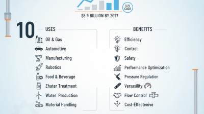
In packaging equipment, pneumatic valves control clamping, sorting, and cutting motions. They also support assembly stations, material handling systems, and simple process controls.
A valve may work during commissioning yet fail under dust, vibration, or frequent cycling. That possibility deserves attention. Record pressure readings, cycle behavior, and replacement dates; these details make later troubleshooting less guesswork.
Get in Touch
570 Alden Road Unit #10, Markham Ontario Canada, L3R 8N5
Quick Links
Featured Products
Industries